Block Diagram of Computer
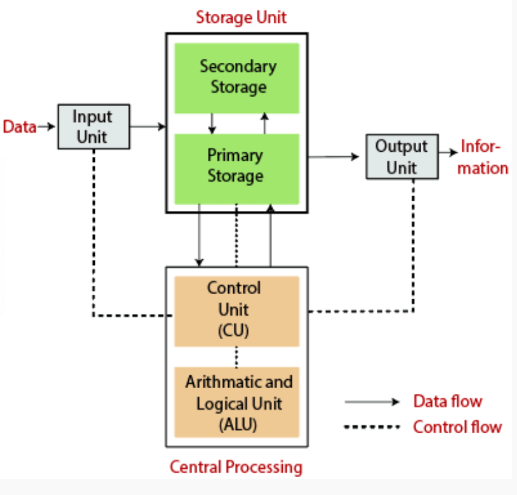
A block diagram of a computer provides a visual representation of the basic components of a computer system and their interactions. Here’s an explanation of the main parts typically found in a computer block diagram:
1. Central Processing Unit (CPU)

- Control Unit (CU): Directs the operation of the processor. It tells the computer’s memory, arithmetic/logic unit, and input and output devices how to respond to the instructions that have been sent to the processor.
- Arithmetic Logic Unit (ALU): Performs arithmetic and logical operations. It’s essentially the calculator of the computer, handling all the mathematical calculations and logical decisions.
2. Memory Unit
- Primary Memory (RAM and ROM): This is where the computer stores data and instructions that are currently in use. RAM (Random Access Memory) is volatile, meaning it loses its data when the power is turned off. ROM (Read-Only Memory) stores critical boot-up instructions and does not lose its data when the power is off.

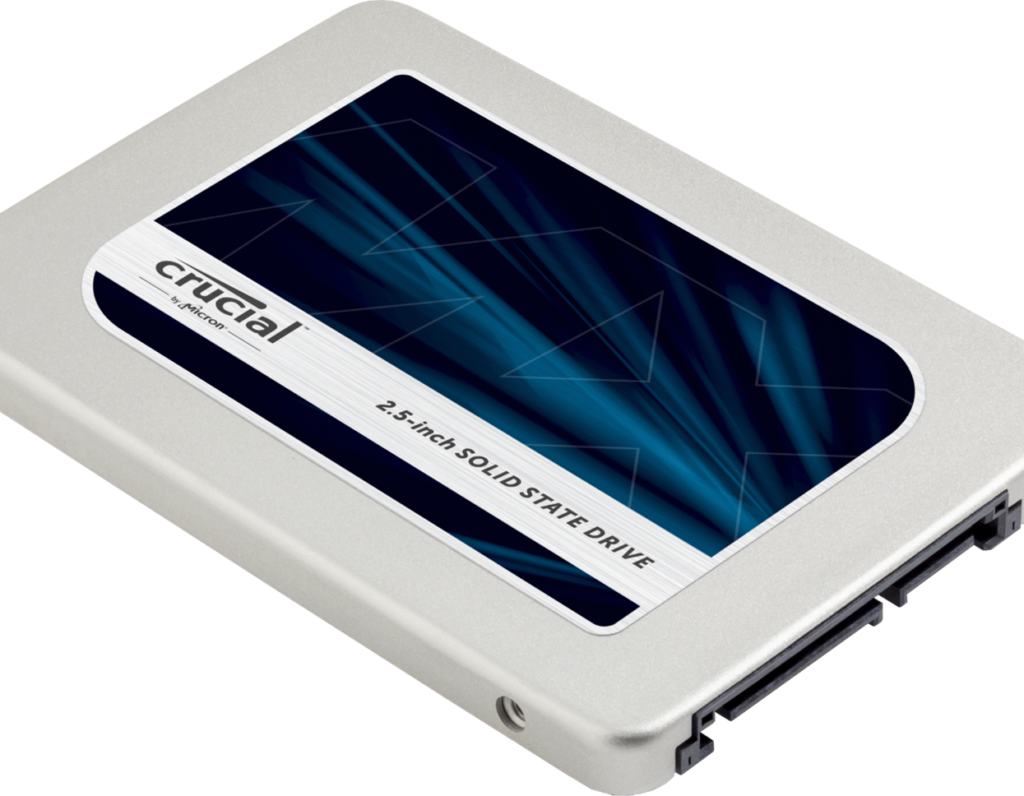
- Secondary Memory: Includes storage devices like hard drives, solid-state drives, and external memory devices. This memory is non-volatile and stores data permanently until it is deleted or overwritten.

3. Input Devices
- These devices allow users to input data into the computer. Examples include keyboards, mice, scanners, and microphones.

4. Output Devices
These devices allow the computer to communicate the results of its processes. Common examples include monitors, printers, and speakers.
5. System Bus
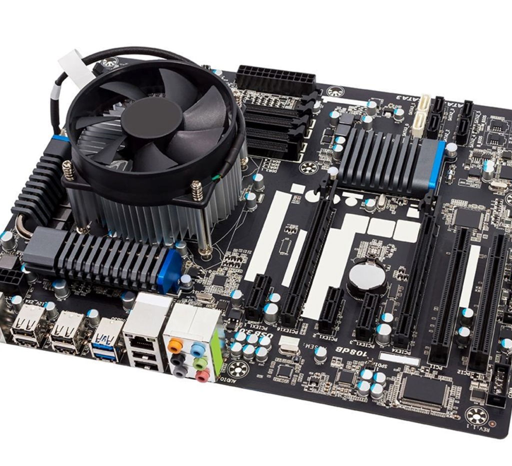
A communication system that transfers data between components inside or between computers. It connects the different parts of the computer, like the CPU, memory, and I/O devices, and consists of the data bus, address bus, and control bus.

6. I/O (Input/Output) Interface
- Acts as a bridge between the CPU and the peripheral devices. It manages the data exchange between the internal system and external devices.
How These Components Interact:
- Data Flow: Data is entered through input devices and stored in the memory. The CPU retrieves instructions and data from the memory and processes them in the ALU.
- Control Flow: The CU interprets instructions from the memory and issues commands to the ALU and other parts of the system.
- Output Generation: The processed data is sent to output devices or stored back in memory for future use.
This structure allows a computer to perform a wide variety of tasks, from simple calculations to complex simulations, by executing instructions stored in its memory and interacting with peripheral devices.
